



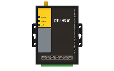
DTU
DTU (Data Transfer Unit) is a wireless data‑transmission module. It transmits data from RS232 / RS485 and other serial ports over wireless networks. It fulfills the requirement of converting short‑range serial‑port communication of industrial equipment into remote wireless communication, enabling users to realize remote data monitoring and management.
Specification parameters
Main Technical Specifications
Item | Specification |
|---|---|
Operating Frequency Band | |
LTE Module | LTE‑FDD: B1/B3/B5/B8LTE‑TDD: B34/B38/B39/B40/B41 |
Antenna | |
Antenna Interface | 1 main‑diversity RF antenna interface for 50 Ω impedance‑matched antenna |
Main RF Characteristics | |
Max. Transmit Power | <23 dbm=""> |
Receiver Sensitivity | <-98.5 dbm=""> |
Power Characteristics | |
Operating Voltage | DC 5~36 V |
Power Consumption | F‑M100‑101. Dial‑up connection: 70~50 mA @12 V2. Data transmission: 55~40 mA @12 V3. Standby (short connection): 33 mA @12 VF‑M100‑111. Dial‑up connection: 26~45 mA @12 V2. Data transmission: 15~28 mA @12 V3. Standby (short connection): 12 mA @12 VF‑M100‑121. Dial‑up connection: 21~25 mA @12 V2. Data transmission: 18~22 mA @12 V3. Standby (short connection): 15 mA @12 V |
Mechanical Characteristics | |
Dimension (L × W × H, mm) | 80 × 58.6 × 22.6 |
Weight | Approx. 180 g |
Environmental Conditions | |
Normal Operating Temperature | ‑35℃ ~ +75℃ |
Extended Operating Temperature | ‑40℃ ~ +85℃ |
Storage Temperature | ‑40℃ ~ +85℃ |
Relative Humidity | ≤90% RH |
Data Transmission | |
Transmission Rate | LTE:‑ FDD: Max. downlink 10 Mbps, max. uplink 5 Mbps‑ TDD: Max. downlink 8.2 Mbps, max. uplink 3.4 Mbps (F‑M100‑10) |
Interfaces | |
Serial Port | 1×RS485 with built‑in 15 kV ESD protection‑ Data bit: 7 / 8 bit‑ Stop bit: 1 / 2 bit‑ Parity: None / Even / Odd‑ Baud rate: 1200 ~ 115200 bps |
Indicator LEDs | Power indicator, communication indicator, online‑status indicator |
Antenna Interface | Standard SMA‑female antenna connector, 50 Ω characteristic impedance |
SIM/UIM Card Interface | Standard drawer‑type SIM/UIM socket, supports 1.8 V / 3 V cards, built‑in 15 kV ESD protection |
Power Interface | Terminal‑block connector |
Supported Protocols | MQTT / TCP / UDP / Modbus‑RTU |
Optional Configurations | |
Communication | Standard: 4GOptional: RS485 / WiFi / LoRa / Ethernet |
Sensor Interfaces | Standard: RS485Optional: UART / I2C / AD / GPIO |
Product Overview
IoT Data‑acquisition DTU
1. Product Overview
DTU (Data Transfer Unit) is a wireless data‑transmission module. It transmits data from RS232 / RS485 and other serial ports over wireless networks. It fulfills the requirement of converting short‑range serial‑port communication of industrial equipment into remote wireless communication, enabling users to realize remote data monitoring and management.
Typical application scenarios include online monitoring and control of user substations and distribution boxes, wireless temperature measurement, environmental monitoring, safety monitoring, fire‑alarm monitoring, fire‑protection supervision, energy auditing, energy‑consumption metering, energy‑saving & emission‑reduction and other fields.
2. Product Features
- Compact Size & Simple Configuration:
Small‑form‑factor unit with multiple configuration options for easy installation and operation. - Automatic Reconnection for High Stability:
Hardware and software watchdog mechanisms provide multi‑layer protection. It supports automatic re‑connection and automatic redial upon disconnection. Adopting TCP heartbeat link detection, it implements re‑connection after drop‑off and cached‑data re‑transmission for stable transmission without packet loss. - Wide Network Coverage:
Full‑netcom design supporting 2G / 3G / 4G networks of three major operators for smooth high‑speed wireless transmission. Dual‑SIM‑card compatibility offers flexible options for users. - Multi‑protocol & Multi‑interface Compatibility:
Multiple interfaces including RS485 are supported, compatible with all serial‑port slave devices for convenient and efficient project deployment.
3. Main Functions
- Data Acquisition & Conversion:
DTU collects switchgear position signals, voltage, current, active/reactive power, power factor, electric‑energy data as well as switch on‑off operation information. It realizes mutual conversion between serial‑port data and IP‑based data. - Real‑time Monitoring:
It monitors operating and fault information of 10 kV lines such as line voltage, line current and zero‑sequence current. With modular processing, it implements remote signalling, remote metering and remote control to support real‑time monitoring for distribution‑network automation. - Remote Communication:
DTU supports multiple communication modes including optical‑fiber, power‑line carrier and wireless communication (GPRS / CDMA etc.) for remote data transmission. - Parameter Configuration & Storage:
Serial‑port‑based parameter setting is available. Configured parameters are saved in internal memory. The device automatically runs according to saved settings after power‑on.
4. Application Topology
Sensors (gas sensor, micro‑meteorological station, temperature‑humidity sensor, explosion‑proof gas sensor, water‑immersion sensor, particle sensor) → RS485/UART/I2C/AD/GPIO → DTU‑HS‑01 (4G Cat1 / WiFi / LoRa / Ethernet) → Smart‑platform supervision terminal → Data large‑screen / Web‑page client / Mobile‑app client (via NB‑IoT, 4G, 5G).
Note: The topology diagram shows the end‑to‑end data flow from field sensing devices to upper‑layer monitoring terminals.
13:21
What are the features of the IoT Data-acquisition DTU?
How does the IoT Data-acquisition DTU ensure data security?
Can the IoT Data-acquisition DTU be used in harsh environments?
Related Products

HAOSHENGBeing Smart, Being Intelligent
From initial concept to final development, our expert product engineers deliver tailored hardware and software solutions-ready to assist you immediately.
Work with trusted partner.
Get Fast, Accurate Quotes Tailored to Your Project
Access complete product information, specifications, and data sheets
Explore Comprehensive Product Details