




Wireless Temperature Monitoring System Solution
1. Introduction
Long‑term power‑grid operation statistics show that most electrical‑equipment faults are caused by continuous high‑temperature operation induced by heavy‑current loading, equipment ageing and insulation degradation. Such faults may further lead to severe consequences including combustion and explosion. Typical accident cases include transformer fire, current‑transformer explosion, cable‑joint melting and switch‑gear fire.




Temperature variation of high‑voltage electrical equipment is a critical indicator for safe and stable power‑system operation. This IoT‑based wireless temperature‑monitoring system detects thermal defects of electrical equipment and circuits, eliminates hidden hazards and guarantees safe power‑grid operation. It addresses the pain point that traditional manual inspection cannot obtain real‑time cable‑junction temperature data, supports the transformation from scheduled patrol‑inspection to condition‑based maintenance, reduces operation‑maintenance costs and mitigates accident losses.
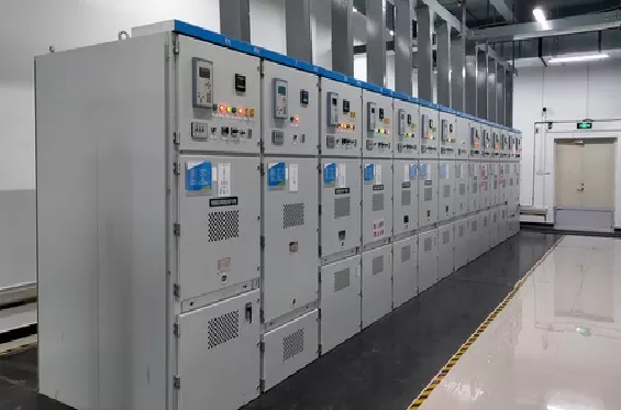
The system applies advanced digital technology and 433 MHz industrial wireless radio‑wave transmission to measure surface / contact temperature of live high‑voltage equipment, such as switch‑blade contacts, main‑transformer bushings, bus couplers, wall‑bushings, cable joints, transformers and handcart‑type circuit‑breakers and other heat‑prone points. Equipped with standard communication interfaces, the system uploads temperature data to monitoring platforms, records real‑time & historical operating temperature of field devices, and realizes predictive maintenance against thermal failures.
01 System Topology
System composition: CT passive temperature sensors, wireless temperature‑acquisition host, DTU / gateway and upper‑level smart monitoring platform.
Passive CT temperature sensors collect temperature at heat‑generating contacts and transmit data via 433 MHz industrial wireless band to the temperature‑acquisition host.
The local host displays all measuring‑point temperatures and triggers local audio‑visual overtemperature alarms.
The host outputs data via wired RS485 or optional WIFI / 4G (DTU) to the smart monitoring platform.
Users access monitoring data via PC‑side client, mobile APP and large‑screen display terminals.
Transmission path: Passive CT Temperature Sensor (433 MHz wireless) → Wireless Temperature‑acquisition Host → Wired RS485 / WIFI / 4G‑DTU → Smart Monitoring Platform → Mobile Terminal / PC Client / Large‑screen Display
The whole system realizes comprehensive monitoring and real‑time perception of measured objects, helping users achieve digital and intelligent management of power equipment.
02 Passive CT Temperature‑measuring Sensor (Model: HS‑CT‑WF)
2.1 Product Introduction
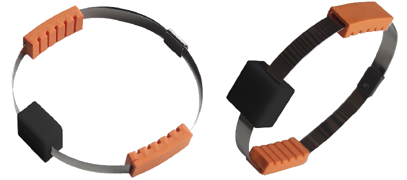
The HS‑CT‑WF passive CT temperature‑measuring sensor realizes online temperature monitoring by wireless transmission. It is directly mounted on high‑voltage electrical equipment. Collected temperature data is transmitted by radio frequency, achieving complete electrical isolation between high‑voltage primary‑side and low‑voltage secondary‑side circuits. No battery is required for sensor operation. Energy is harvested by CT induction from busbar alternating current.
2.2 Product Features
Safe & Reliable, No Modification to Primary Circuit Complete physical high‑low‑voltage electrical isolation via pure‑wireless 433 MHz transmission. No disassembly or re‑wiring of existing equipment. Housing adopts high‑temperature‑resistant flame‑retardant material with silicone potting, suitable for outdoor deployment. Installation uses dedicated steel straps and cushion pads for quick strapping‑mounting.
Advanced Wireless Technology Adopts industrial‑grade digital 433 MHz wireless transmission. Built‑in data error‑correction algorithm suppresses mutual radio‑signal interference. It brings no interference or impact to primary power equipment.
Long‑distance Transmission, Expandable & Easy Deployment Open‑area wireless transmission distance ≥ 300 meters. One host supports up to 240 sensors. No field wiring is required for sensor installation without altering original electrical structures of switchgears.
10‑year Long Service Life, Battery‑free Built‑in high‑precision CT energy‑harvesting unit. Energy harvesting starts at busbar current ≥ 5 A. No lithium‑battery inside. Risks such as battery leakage and high‑temperature swelling‑ignition are completely eliminated. Designed service life reaches 10 years. No sensor replacement throughout the switchgear lifecycle, reducing power‑off maintenance frequency.
2.3 Technical Specifications (HS‑CT‑WF Passive CT Temperature‑measuring Sensor)
Parameter Item | Specification |
|---|---|
Temperature Measuring Range | ‑40℃ ~ 125℃ |
Measurement Accuracy | ±0.5℃ at ambient temperature; ≤±1℃ full‑range |
Temperature Resolution | 0.1℃ |
Communication Mode | 433 MHz industrial wireless |
Power‑supply Mode | CT induction energy‑harvesting; startup current ≥ 5 A |
Wireless Transmission Distance | ≥ 300 m (open‑area environment) |
Service Life | 10 years |
Operating Temperature | ‑40℃ ~ +85℃ |
Maximum Withstand Temperature | 155℃ for 2 hours; 250℃ for ≤ 4 seconds |
Installation Method | Steel‑strap strapping‑mounting |
Overall Dimension | 26 mm × 22 mm × 10 mm |
Ingress Protection Rating | IP65 |
03 Wireless Temperature‑acquisition Host (Model: HS‑CT‑HF‑S / HS‑CT‑HF‑G)
3.1 Product Introduction
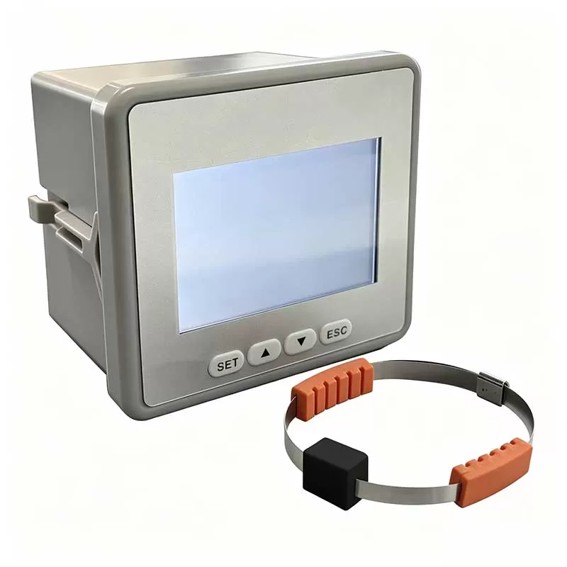
The HS‑CT‑HF series wireless temperature‑acquisition host receives wireless temperature data from up to 240 passive CT sensors. It displays real‑time temperature of each measuring point locally, triggers audio‑visual overtemperature alarms, and uploads data to upper‑level monitoring systems. Historical‑data statistics and analysis support early warning for equipment thermal faults and guarantee reliable device operation.
HS‑CT‑HF‑S: Standard version, RS485+WIFI dual communication
HS‑CT‑HF‑G: 4G customized version, RS485+WIFI+4G triple‑mode communication
3.2 Product Features
Multiple‑mode Standard Communication Interfaces Standard RS485 & WIFI interfaces; optional customized 4G. RS485 complies with Modbus‑RTU; WIFI supports Modbus‑TCP / MQTT. Seamlessly connects to PLC, SCADA, configuration software and third‑party power‑monitoring platforms. No proprietary backend platform binding.
Large‑capacity Multi‑channel Data Acquisition Single host supports maximum 240 passive temperature‑measuring sensors. Real‑time signal acquisition, data recording, local display and alarm processing are supported.
Local & Remote Overtemperature Alarm Overtemperature anomalies are highlighted in red on local color screen together with audio‑visual prompt. Alarm events can be uploaded to remote platforms for notification via APP, SMS, WeChat mini‑program and PC terminals.
Local Configuration via PC Upper‑computer Software Parameters including alarm thresholds and reporting cycles can be configured on‑site by PC software. Password permission management is supported.
Industrial‑grade Hardware & Convenient Installation 3.2‑inch color LCD screen (320*240 resolution) with 4 function keys. Embedded cabinet‑mount installation. Snap‑fit housing prevents unintended disassembly by non‑professional personnel.
3.3 Technical Specifications (HS‑CT‑HF Wireless Temperature‑acquisition Host)
Parameter Item | Standard Specification |
|---|---|
Receiving Capacity | Max. bind 240 passive temperature‑measuring sensors |
Display Screen | 3.2‑inch color LCD; resolution 320*240 |
Local Operation | 4 function keys; password‑permission setting supported |
Local Alarm | Overtemperature anomaly highlighted in red + audio‑visual prompt |
Standard Communication Interfaces | RS485 (Modbus‑RTU), WIFI (Modbus‑TCP / MQTT) |
Optional Communication | 4G (customizable frequency bands for HS‑CT‑HF‑G) |
Power‑supply Input | AC220 V; optional DC12/24 V |
Whole‑unit Power Consumption | ≤ 10 VA |
Operating Temperature | ‑20℃ ~ +70℃ |
Operating Humidity | ≤ 90% RH, non‑condensing |
Cut‑out Dimension | 92.5 mm × 72.95 mm |
Installation Method | Embedded cabinet mounting |
Configuration Mode | Local configuration via PC upper‑computer software |
Customizable Items | Access capacity, communication protocols, alarm thresholds, appearance, LOGO, packaging |
04 Smart Monitoring Platform
4.1 Product Features
Secure Permission‑based Architecture Three‑level account‑authority design realizing data isolation for different users and hierarchical permission management for primary & sub‑accounts.
User‑friendly Human‑machine Interaction Real‑time online viewing of monitoring data; export of monitoring data from multiple stations.
Rich Management Functions Personnel management, operation‑job records, station management, equipment management, alarm‑event records and statistical analysis.
Typical Monitoring Installation Points
Moving / static contacts and contact boxes of high‑low‑voltage switchgears
Connection joints of main busbars and branch busbars
Cable terminal joints and cable intermediate joints
Heat‑generating positions of current transformers and wiring terminals
Conductive connection parts of ring main units, box‑type transformers and outdoor distribution boxes
Application Scenarios
Power‑grid Industry: Substations, power‑distribution rooms, box‑type substations, ring main units, switching stations
Industrial‑commercial Power Distribution: Factory high‑low‑voltage power‑distribution rooms, UPS cabinets in data centers, power‑distribution rooms of shopping malls & office buildings
New‑energy Power Stations: PV box‑type transformers, wind‑power step‑up stations, energy‑storage switchgears and energy‑storage‑cabin busbar temperature‑measurement
Rail Transit: Metro power‑distribution rooms, tunnel ring main units, station high‑voltage switchgears
Municipal Infrastructure: Power‑distribution rooms of hospitals, schools and government buildings, power‑distribution equipment in underground utility tunnels