




The Definitive Guide to Cable Link Box Condition Monitoring in the AIoT Era
High-voltage (HV) underground power cables form the backbone of modern power distribution networks. These insulated lifelines transmit vast amounts of electricity through dense urban corridors, industrial clusters, and offshore wind connections. Yet, operators often overlook one vulnerable component in this infrastructure: the cable link box.
A single link box failure can trigger catastrophic cable damage, severe service disruptions, and costly emergency repairs. As power networks become more complex, manual inspection schedules no longer provide sufficient risk mitigation. Power asset managers are transitioning to real-time Cable Link Box Condition Monitoring to anticipate faults before they happen.
Leading hardware developers like HAOSHENG deliver industrial-grade sensing platforms built for these challenging environments. If you are upgrading substation infrastructure or retrofitting legacy underground circuits, request a technical consultation with HAOSHENG to evaluate your deployment requirements.
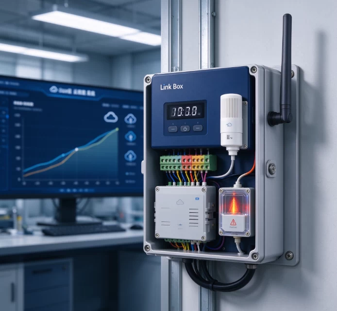
Why Cable Link Box Condition Monitoring Matters
Link boxes serve as the critical interface points for cable metallic sheaths. While the main cable body benefits from heavy factory insulation, the link box exposes connections to physical stress, moisture, and electrical surges. Continuous surveillance protects the integrity of the entire circuit.
Critical Role in High-Voltage Systems
In high-voltage single-core AC cables, current flowing through the conductor induces a voltage along the metallic sheath. Uncontrolled sheath voltages pose safety hazards to maintenance personnel and can break down cable jackets.
Engineers deploy link boxes to manage these voltages using three primary methods:
- Single-point bonding: Grounding the sheath at one end while leaving the other end protected by a Sheath Voltage Limiter (SVL).
- Solid bonding: Grounding both ends directly, which permits circulating currents that generate thermal losses.
- Cross-bonding: Transposing the sheaths of adjacent phases across balanced minor sections to cancel out induced voltages and minimize circulating currents.
Common Failure Modes and Destructive Consequences
Link boxes operate in subterranean pits, manholes, and trackside enclosures. These locations expose equipment to harsh operating conditions. Common failure mechanisms include:
- Water Ingress and Submersion: High humidity and floodwaters degrade internal insulation, causing phase-to-ground flashovers.
- SVL Degradation: Metal-oxide varistors degrade after absorbing repeated switching surges or lightning strikes, eventually shorting to ground.
- Loose Internal Terminations: Thermal cycling loosens bolted busbars, triggering localized overheating and thermal runaway.
- Cable Sheath Theft or Severance: Stolen or disconnected grounding copper leads to unconstrained sheath voltages exceeding several kilovolts.
Bottlenecks of Traditional Manual Inspections
Historically, technicians conducted spot checks with handheld thermal cameras and clamp meters every six to twelve months. This approach presents severe operational liabilities:
- Intermittent defects, such as transient overvoltages or load-dependent overheating, are missed between inspection cycles.
- Confined-space entry into manholes requires street closures, dewatering, gas testing, and extensive labor hours.
- Maintenance crews face direct arc-flash risks when opening aged or compromised boxes under load.
The AIoT Revolution in Link Box Monitoring
The convergence of Artificial Intelligence and the Internet of Things (AIoT) replaces reactive firefighting with predictive asset management. Connected link boxes transform passive junction points into intelligent grid sentinels.
Transition to Predictive Maintenance
Predictive maintenance moves utilities away from calendar-based work orders. Instead, edge sensors track degradation indicators in real time. Maintenance teams dispatch crews only when analytical models identify an anomalous trend, saving capital expenditure and reducing operational risk.
Hardware Layer: Low-Power Sensors and Energy Harvesting
Underground manholes rarely offer auxiliary low-voltage AC power. AIoT monitoring hardware resolves this constraint through ultra-low-power microcontrollers and specialized energy harvesting. Devices harvest energy directly from primary cable magnetic fields using split-core current transformers, backed by long-life lithium batteries.
Edge AI: On-Device Analytics
Modern field hardware runs lightweight anomaly-detection algorithms at the node level. By computing root-mean-square (RMS) currents, crest factors, and thermal differentials on site, edge nodes prevent data saturation. They operate quietly during normal conditions and transmit high-frequency telemetry immediately when parameters cross predefined thresholds.
Cloud Layer: Digital Twins and Fleet Analytics
At the central control center, cloud systems integrate incoming data streams into comprehensive digital twin models. Machine learning algorithms evaluate historical trends across thousands of link boxes, correlating ambient temperatures, feeder load profiles, and seasonal moisture levels to forecast remaining component life.
Key Parameters to Monitor in Modern Smart Link Boxes
A comprehensive Cable Link Box Condition Monitoring system tracks multiple physical and electrical characteristics simultaneously to pinpoint faults accurately.
Sheath Circulating Current Monitoring
Sheath circulating current provides direct insight into cable health. In a well-balanced cross-bonded system, sheath current generally remains below 5% to 10% of the primary conductor current. An increase in this ratio indicates distinct faults:
- Insulation breakdown between adjacent phases or sections.
- Open circuits caused by stolen bonding cables or blown SVL links.
- Flooded link boxes altering phase-to-ground impedance paths.
Partial Discharge (PD) Detection
Partial discharge activity serves as the earliest warning sign of impending insulation failure. High-Frequency Current Transformers (HFCT) or transient earth voltage (TEV) sensors mounted inside the link box capture minute, high-frequency current pulses resulting from void ionization or tracking along insulation surfaces.
Thermal Monitoring
Contact resistance across busbars generates heat in direct proportion to current square ($I^2R$). Non-contact infrared temperature sensors or direct-contact magnetic RTDs monitor internal busbar joints, comparing the readings against ambient box temperatures to flag abnormal temperature rises before insulation melting occurs.
Sheath Voltage Limiter (SVL) Health and Surge Counting
Surge arresters degrade over time. Continuous microampere-level leakage current monitoring determines whether the zinc oxide disks have deteriorated. Integrated pulse counters verify whether an SVL has operated during a network switching event or lightning strike.
Environmental and Physical Security Surveillance
External conditions often trigger internal link box failures. Reliable monitoring systems integrate basic environmental sensors:
- Water level/submersion sensors: Alerts operators when manholes flood and water breaches IP68 link box seals.
- Relative humidity sensors: Identifies internal condensation before dielectric breakdown occurs.
- Door status and tamper switches: Detects unauthorized access, vandalism, or copper theft immediately.
System Architecture: From Sensor to Substation SCADA
Implementing an end-to-end monitoring solution requires a robust three-tier architecture engineered to endure extreme electromagnetic interference.
1. Non-Intrusive Sensing Layer
Engineers favor non-intrusive sensors during retrofits. Split-core Rogowski coils and openable HFCTs clamp directly over sheath bonding conductors without disconnecting ground leads. Industrial-grade solutions from HAOSHENG incorporate heavy electromagnetic shielding to suppress cross-phase noise and maintain clean sensor output.
2. Robust Transmission Layer
Transmitting data out of subterranean concrete pits demands resilient wireless configurations. Common communication topologies include:
- NB-IoT (Narrowband IoT): Offers deep structural penetration to broadcast directly from subsurface pits to public cellular towers.
- LoRaWAN: Well suited for private utility networks, allowing low-power transceivers to transmit through pit covers to a local substation gateway.
- Short-Range RF to Surface Repeaters: Uses sub-GHz links from inside the box to an antenna integrated into a surface street bollard, which then transmits over 4G/5G.
3. Enterprise Software and SCADA Integration
Edge nodes feed data back to centralized asset management systems. Open integration frameworks use standard protocols such as IEC 61850, Modbus TCP, and MQTT. Asset managers view live thermal profiles, receive automated alarms, and run predictive maintenance models through centralized operations interfaces.
Business Value and ROI for Utilities and Heavy Industry
Deploying automated monitoring equipment requires capital investment. However, the business case yields substantial financial returns across the equipment lifecycle.
Mitigating Unplanned Outages (SAIDI / SAIFI)
Regulators penalize power distribution companies for customer interruptions. A catastrophic failure in a cross-bonded transmission cable can disable regional distribution networks for days. Early identification of thermal anomalies or sheath disconnection preserves network stability and protects operational reliability indices.
Reducing Field Maintenance OPEX
Manual link box inspections require dedicated road crews, specialized safety equipment, traffic management, and manhole pumping teams. Automated online monitoring eliminates routine scheduled visits. Field teams mobilize only when sensors identify actionable degradation, reducing field operational expenses by over 60%.
Extending High-Voltage Asset Life (CAPEX Optimization)
Uncontrolled sheath circulating currents cause thermal stress in main conductor insulation, accelerating thermal aging. Maintaining optimal sheath isolation preserves primary insulation, ensuring cables operate safely through their full 40-year design life without premature replacement.
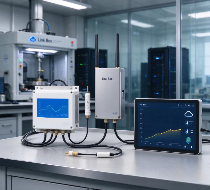
Engineering Checklist: Selecting the Right Solution
When specifying Cable Link Box Condition Monitoring equipment, evaluate prospective vendors against this operational criteria list:
- Submersible Ingress Rating: Verify true IP68 compliance tested for continuous submersion under water heads exceeding 2 meters for extended periods.
- Electromagnetic Immunity: Ensure compliance with IEC 61000-4 standards to prevent false triggers during high-voltage switching transients or through-faults.
- Non-Outage Installation: Check whether sensor designs allow live installation without requiring primary feeder shutdowns or ground disconnections.
- Cybersecurity Protocols: Insist on encrypted communications (AES-128 minimum) and secure firmware updates over-the-air (FOTA) to protect edge devices from intrusion.
- Standard Communication Compliance: Confirm that software gateways natively support DNP3, IEC 60870-5-104, or IEC 61850 for seamless SCADA integration.
Frequently Asked Questions (FAQ)
Q1: What is an intelligent or smart cable link box?
A1: A smart cable link box is an upgraded high-voltage sheath bonding enclosure fitted with internal sensors, edge computing hardware, and wireless communications. Unlike passive link boxes, it continuously measures sheath currents, temperature, moisture, and partial discharge, streaming diagnostic data to substation automation systems without human intervention.
Q2: What is the normal threshold for cable sheath circulating current?
A2: In a properly balanced, cross-bonded high-voltage cable system, the sheath circulating current should generally remain below 10% of the primary conductor load current, with optimal systems operating below 5%. If sheath current exceeds 20% of load current, engineering teams should immediately investigate for incorrect bonding connections, degraded SVLs, or sheath-to-ground insulation faults.
Q3: How do wireless monitoring units transmit data from sealed underground manholes?
A3: Underground systems use high-gain external antennas, low-frequency radio waves, or specialized cellular protocols designed for deep penetration, such as NB-IoT. In challenging sites beneath reinforced concrete or solid metal manhole covers, installers place a remote antenna on a nearby street post or mount an antenna directly into a non-metallic composite pit lid.
Q4: Can monitoring hardware be retrofitted to existing energized link boxes?
A4: Yes. Modern condition monitoring systems use split-core sensors, including split-core Rogowski coils and openable High-Frequency Current Transformers (HFCTs). These components clamp around grounding leads and link connections without opening the primary circuit or breaking the earth path, enabling installation without power interruptions.
Q5: How does Sheath Voltage Limiter (SVL) failure impact network safety?
A5: An SVL typically fails in one of two modes: short-circuit or open-circuit. A shorted SVL introduces an unintended ground point, converting a single-point or cross-bonded arrangement into a solid-bonded loop that drives high circulating currents and causes severe cable overheating. An open SVL leaves the sheath unprotected during lightning strikes and switching surges, creating dangerous flashovers and presenting fatal shock hazards to nearby personnel.
Protect Your High-Voltage Network Today
Maintaining high-voltage cable reliability requires visibility over every link in the circuit. Manual inspections leave too many blind spots along modern power paths. Automated, continuous Cable Link Box Condition Monitoring offers the actionable visibility needed to eliminate unplanned outages, safeguard personnel, and maximize underground asset life.
HAOSHENG engineers robust monitoring solutions designed for the world's most demanding utility networks and heavy industrial installations. Contact our engineering team today to discuss your project specifications, request a formal quote, or arrange an on-site technology demonstration.