




Subterranean Grid Safety: Smart Link Box Flooding Monitoring Device
High-voltage (HV) and medium-voltage (MV) underground power distribution networks represent the lifeblood of modern metropolitan and industrial infrastructure. As utilities transition overhead lines to subterranean cable tunnels, trenches, and direct-buried ducts to enhance urban aesthetics and weather resilience, new operational vulnerabilities emerge. Primary among these vulnerabilities is the integrity of cross-bonding and earth-continuity link boxes installed in subterranean pits, manholes, and cable vaults. Submerged link boxes present an invisible threat to electrical transmission, catalyzing dielectric degradation, premature sheath breakdown, and catastrophic outages. Modernizing this infrastructure requires autonomous sensing capabilities, where adopting an industrial-grade Link Box Flooding Monitoring Device has transitioned from an optional enhancement to an operational baseline.
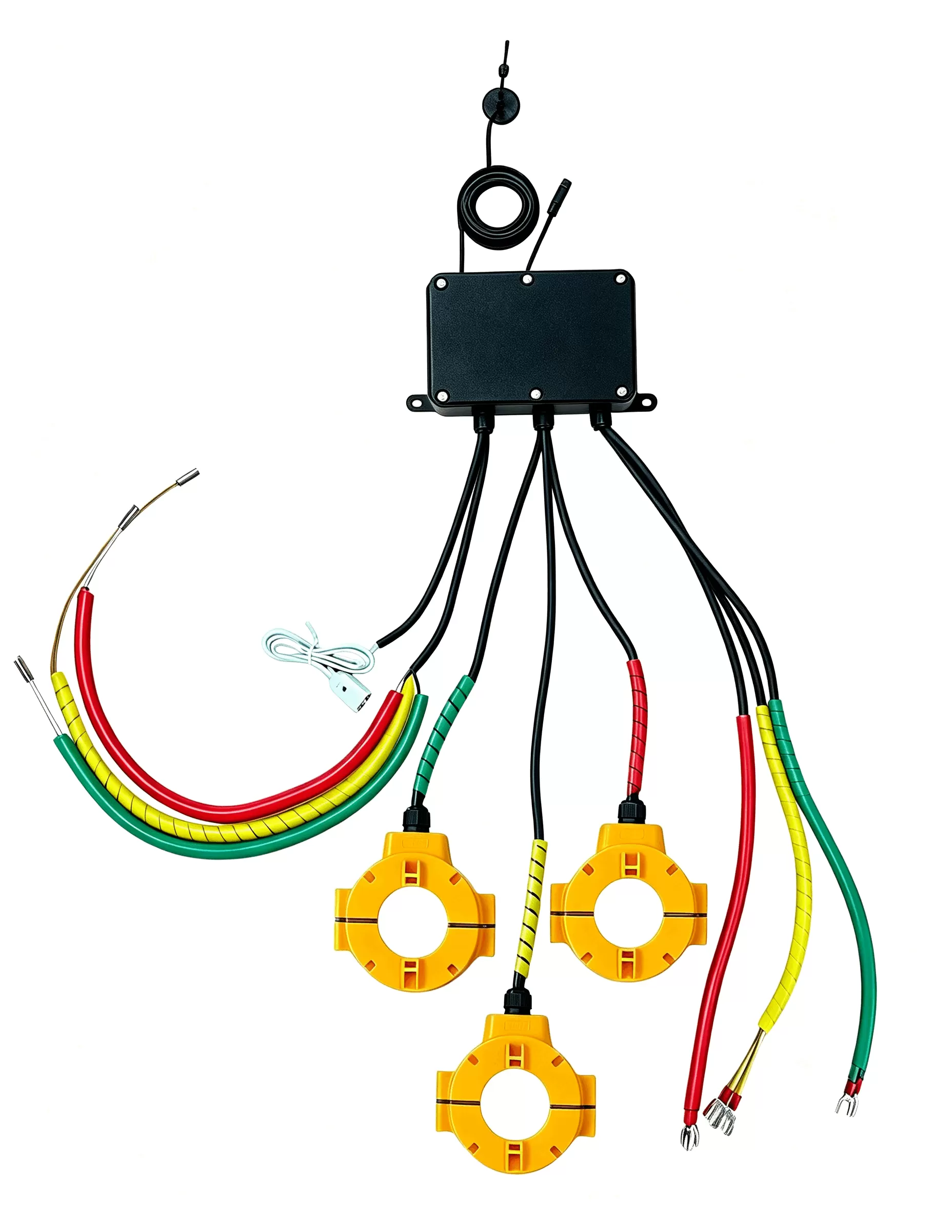
The Subterranean Cable Ecosystem and Water Ingress Challenges
Underground insulated power cables utilize metallic sheaths to equalize electrical stress, carry capacitive charging currents, and provide a path for fault currents. To suppress induced voltages and mitigate circulating currents that generate thermal losses and de-rate cable ampacity, engineers implement specialized sheath bonding configurations, primarily cross-bonding and single-point bonding systems. Link boxes house these critical connections, alongside Sheath Voltage Limiters (SVLs) designed to clamp transient overvoltages triggered by lightning or switching surges.
Subterranean link boxes occupy hostile operational environments. Manholes and cable chambers are intrinsically susceptible to flooding driven by surface runoff, elevated water tables, municipal drainage failures, and seasonal storms. When water penetrates a standard link box enclosure, the dielectric properties of the internal atmosphere collapse. Water creates low-impedance bypass paths across the SVLs, initiates galvanic corrosion of contact terminals, and converts transient protection components into conductive fault paths.
Undetected immersion alters the sheath earthing topology. Circulating currents spike uncontrolled through the water volume and ground paths, generating severe localized heating. This thermal escalation accelerates the degradation of adjacent cross-linked polyethylene (XLPE) insulation jackets. Left unmitigated, prolonged submersion culminates in phase-to-ground faults, severe equipment destruction, and lengthy outages that carry heavy regulatory penalties and immense repair expenses.
Technical Architecture of a Link Box Flooding Monitoring Device
Engineering a telemetry and sensing system capable of long-term deployment inside sealed underground environments requires strict hardware discipline. The physical environment lacks auxiliary power, experiences extreme humidity fluctuations, and attenuates standard radio frequencies. Consequently, an advanced Link Box Flooding Monitoring Device incorporates dual-sensing mechanisms, ultra-low-power embedded computing, and durable industrial containment.
Multi-Modal Liquid Detection Instrumentation
Precision liquid monitoring demands immunity to false alarms induced by ambient condensation, oil residues, and silt accumulation. Reliable field equipment employs complementary sensing technologies:
- Conductive Point-Level Sensors: Gold-plated or titanium electrode arrays positioned at calibrated elevations within the link box enclosure or manhole basin. When conductive liquid bridges the gap, it completes a micro-current circuit, generating an instantaneous hardware interrupt that wakes the device microcontroller from deep sleep.
- Hydrostatic Pressure Transducers: Piezoresistive silicon pressure sensors housed in 316L stainless steel submersed housings. These sensors measure the exact liquid column height above the sensor datum, converting hydrostatic pressure into a continuous liquid level metric. This continuous data enables the calculation of water accumulation rates rather than mere binary presence.
- Optoelectronic Interface Sensors: Utilized in environments with high hydrocarbon exposure, these sensors leverage the refractive index disparity between air and liquid against an optical prism to confirm presence without relying solely on electrical conductivity.
Micro-Power Embedded Processing and Energy Budgets
Subterranean infrastructure precludes direct grid connections. Operational architectures developed by HAOSHENG integrate micro-power components powered by high-energy-density Lithium Thionyl Chloride (Li-SOCl2) battery chemistry. These power cells maintain flat discharge profiles and operate reliably from -40°C to +85°C. System firmware enforces aggressive sleep profiles, keeping quiescent current draw beneath 5 microamps during baseline monitoring. The microcontroller activates high-power transmission modules only upon threshold breaches or scheduled health-check heartbeats, ensuring autonomous field maintenance intervals exceeding five to eight years.
Chassis Hardening and Environmental Isolation
The mechanical housing of a Link Box Flooding Monitoring Device must withstand continuous submergence under substantial hydrostatic heads, chemical exposure to industrial runoff, and mechanical impacts. Equipment architectures require ingress protection ratings of IP68 (continuously submerged to a minimum depth of three meters for 72 hours) or IP69K. Enclosure materials typically include marine-grade polycarbonates, polybutylene terephthalate (PBT), or anodized aluminum alloys capable of neutralizing hydrogen sulfide and hydrocarbon-induced stress cracking.
IoT Telemetry and Protocol Integration in Subterranean Topologies
Transmitting telemetry from a subterranean Link Box Flooding Monitoring Device involves penetrating cast-iron manholes, reinforced concrete slabs, and subterranean soil strata. Standard wireless protocols like classic Wi-Fi and Bluetooth fail due to severe physical attenuation. AIoT subterranean engineering relies on Low-Power Wide-Area Network (LPWAN) protocols operating at sub-gigahertz frequencies.
Wireless Transmission Physics
Narrowband IoT (NB-IoT) and Long Range (LoRaWAN) operate on licensed and unlicensed sub-GHz bands, respectively. Their prolonged symbol durations and superior link budgets (exceeding 160 dB in NB-IoT networks) allow RF signals to penetrate urban surface infrastructure. In scenarios where manhole covers are solid cast iron, low-profile, surface-mounted "puck" antennas or composite manhole cover replacements are integrated to establish uncompromised line-of-sight propagation to local cellular base stations or private gateways.
Industrial Protocol Harmonization
Edge devices package measurement parameters, battery state of health (SoH), temperature, and alarm states into lightweight payloads using protocols such as MQTT, CoAP, or structured binary UDP frames. In industrial grid implementations, intelligent solutions developed by HAOSHENG utilize optimized RF transceivers that deliver this data to central processing middleware. The telemetry converts into standardized IEC 60870-5-104 or DNP3 protocol strings, facilitating seamless native injection into utility SCADA (Supervisory Control and Data Acquisition) and Asset Performance Management (APM) suites.
Asset Health Indexing and Predictive Maintenance Shift
Traditional maintenance regimes for underground cable routes rely on scheduled, manual inspections. Maintenance crews navigate heavy traffic, physically open manholes, pump out stagnant water, and conduct visual surveys of link box enclosures. This paradigm suffers from significant inefficiencies. It exposes field personnel to confined-space hazards and introduces long temporal blind spots between inspection cycles, during which water ingress can occur and persist undetected.
Deploying automated monitoring equipment transforms link box asset health indexing from a reactive schedule to a condition-based, predictive framework:
- Instantaneous Threat Escalation: Operations centers receive alerts within seconds of water ingress crossing critical safety thresholds, enabling targeted dispatch of pumping crews before moisture degrades electrical insulation.
- Rate-of-Rise Predictive Analysis: Continuous hydrostatic data uncovers external drainage system failures by tracking water accumulation velocity, allowing engineers to resolve civil drainage defects before seasonal storms arrive.
- Elimination of Unnecessary Manhole Entries: Automated remote confirmations of dry, stable link box interiors eliminate manual inspection protocols, drastically lowering operational expenditures and reducing street-level work-zone disruptions.
- Enhanced Insulation Diagnostics: Correlating link box moisture data with partial discharge (PD) readings prevents engineers from misdiagnosing water-induced surface discharges as internal cable insulation breakdown, avoiding expensive and unnecessary cable replacements.
Installation Methodologies and Operational Best Practices
Successful long-term deployment of monitoring devices demands strict adherence to installation protocols tailored to high-voltage subterranean environments. The proximity of high electrical stresses necessitates non-intrusive mounting techniques that preserve the mechanical and electrical integrity of the parent infrastructure.
First, the sensor probe placement must match the fluid dynamics of the specific link box chamber. Secondary drainage collection sumps are the ideal mounting location for primary conductive sensors, capturing early ingress before liquid reaches the base plate of the link box enclosure. The primary unit chassis should be mounted as high as practical inside the manhole vault, anchoring to non-conductive bracketry to avoid ground-loop formation.
Second, cable entries must utilize compression-molded double-O-ring cable glands, augmented by hydrophobic sealing gels. Connectors must be certified for continuous underwater operation. Installers must avoid running sensor cables parallel to single-core high-voltage power cables to avoid high electromagnetic induction that could induce transient overvoltages within the low-voltage sensor circuitry.
Third, antenna positioning determines the long-term reliability of LPWAN connectivity. Field technicians must record the Reference Signal Received Power (RSRP) and Signal-to-Noise Ratio (SNR) before permanently sealing the installation. Where subterranean structures create impenetrable RF shielding, external antennas potted in high-impact polyurethanes must be routed to the underside of ventilation grates or deployed through core-drilled conduits to road-surface level.
Addressing Common Field Challenges
Sustained reliability requires engineering solutions for specific physical realities encountered in underground utility vaults.
Biofouling and mineral deposition represent constant challenges. In subterranean vaults, stagnant water carries dissolved calcium carbonates, iron silicates, and organic biomass. Over months of cyclical wetting and drying, these substances form crusts over sensor electrodes, potentially blinding conductive circuits or blocking pressure diaphragms. Mitigating this issue requires anti-fouling geometries, including wide-gap electrode pins, sacrificial zinc rings, and self-cleaning capacitive sensor surfaces that register changes in dielectric constant without bare-metal liquid exposure.
Thermal stability must also be engineered into the electronics. While subterranean depths insulate equipment from daily atmospheric temperature peaks, proximity to high-amperage cables elevates ambient ambient temperatures within the vault. The deployment of a dedicated Link Box Flooding Monitoring Device guarantees continuous telemetry even when vault ambient conditions swing between freezing winters and thermal build-ups approaching 60°C during peak electrical load periods.
Frequently Asked Questions
What failure modes occur when an underground cable link box becomes flooded?
Flooding introduces water across Sheath Voltage Limiters (SVLs) and busbars within the link box. This creates low-impedance alternate pathways for electrical current, driving circulating currents through the sheath bonding network. These currents generate excessive thermal energy, corrode termination joints, degrade SVL arrestor discs, and accelerate dielectric breakdown of the cable outer jacket. Ultimately, unaddressed immersion leads to high-voltage earth faults and service interruptions.
How does a Link Box Flooding Monitoring Device transmit data through solid manhole covers?
The device leverages sub-gigahertz LPWAN telemetry, such as NB-IoT or LoRaWAN, which features high link budgets designed for signal penetration through concrete and asphalt. In instances involving solid cast-iron manhole covers that create a Faraday cage, technicians utilize ultra-low-profile puck antennas mounted through adjacent pavement, composite radio-transparent manhole lids, or antennas routed directly beneath roadside ventilation grates.
Can the monitoring device distinguish between ambient condensation and actual flooding?
Industrial units avoid false alarms from high ambient humidity and wall condensation by using dual-threshold sensing logic. Point-level electrodes require continuous conductive contact over a pre-calibrated surface area, while hydrostatic pressure sensors confirm fluid head pressure above atmospheric baselines. Firmware-level debouncing filters ignore micro-droplet bridges caused by high ambient condensation.
What is the typical battery lifespan of an autonomous flooding monitoring sensor?
Operating on high-capacity Lithium Thionyl Chloride (Li-SOCl2) power cells, typical lifespans range from five to ten years. Longevity depends on data transmission intervals. Standard configurations maintain the internal processor in ultra-low-power sleep mode, waking only to transmit periodic diagnostic heartbeats (e.g., once daily) or triggering dynamic interrupts instantly if liquid thresholds are breached.
Can this device be integrated into our utility SCADA or asset management software?
Yes. Contemporary monitoring solutions use open, flexible architectures. Telemetry transmitted over cellular or LPWAN backhauls to cloud or on-premise servers is decoded from MQTT, CoAP, or JSON formats and mapped into industrial SCADA protocols such as IEC 60870-5-104, Modbus TCP, or DNP3. This architecture enables native integration into operational dispatch centers without requiring specialized standalone viewer software.
Are these devices certified for explosive subterranean environments?
Subterranean cable chambers occasionally accumulate methane, sewer gases, or volatile hydrocarbons. Leading monitoring solutions designed for industrial vault installations offer intrinsic safety certifications (such as ATEX / IECEx Zone 0 or Zone 1 compliance), preventing any electrical spark discharge from the sensor circuitry or battery unit from igniting ambient combustible gases.
Engineering Consultation and System Deployment
Securing subterranean transmission networks against water ingress requires robust, hardened sensor instrumentation tailored specifically to the electrical and environmental challenges of high-voltage cable environments. Selecting the appropriate Link Box Flooding Monitoring Device requires a comprehensive review of your grid topology, subterranean radio-frequency profiles, and existing SCADA communications architectures.
For custom engineering consultations, detailed sensor interface drawings, technical data sheets, and commercial project quotations, contact the HAOSHENG technical engineering team. Our specialist application engineers assist transmission and distribution system operators in tailoring, piloting, and scaling intelligent link box telemetry solutions worldwide.